





What is Pipeline Centrifugal Pump
Release time: 2026-08-04
Table of Contents
Fluid dynamics and mechanical engineering are the lifeblood of modern industrial operations. From municipal water treatment facilities to towering commercial skyscrapers, the ability to move liquids efficiently, safely, and continuously is a non-negotiable requirement. While there are countless mechanisms designed to facilitate this movement, one specific category of equipment stands out for its seamless integration and unparalleled efficiency. This brings us to a foundational question often asked by facility managers, procurement specialists, and junior engineers alike: What is Pipeline Centrifugal Pump?
In this comprehensive guide, we will dissect the mechanical ingenuity behind these essential devices. We will explore their core working principles, structural classifications, diverse industrial applications, and the maintenance protocols required to keep them running at peak performance. Whether you are designing a complex HVAC system or upgrading a petrochemical processing plant, understanding the nuances of these inline fluid transporters is critical to optimizing your operational efficiency.
What is Pipeline Centrifugal Pump?
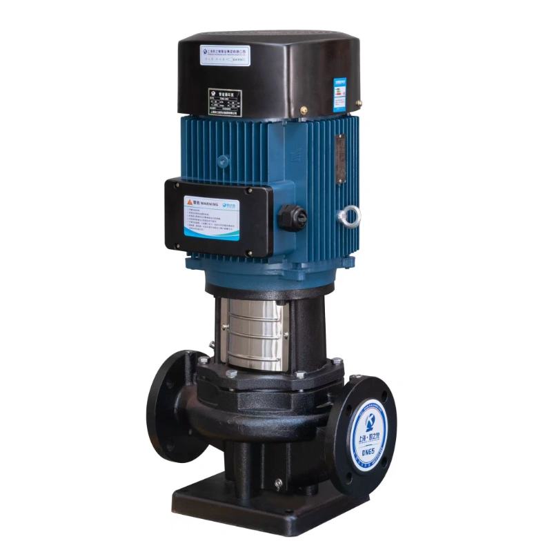
A pipeline centrifugal pump—frequently referred to as an inline pump—is a highly efficient fluid transportation device engineered for direct integration into existing pipework. Unlike traditional end-suction pumps that feature staggered or perpendicular inlet and outlet configurations, this specific machinery boasts a coaxial linear layout. This means that both the suction (inlet) and discharge (outlet) flanges share the exact same diameter and are positioned on the same straight axis.
This unique geometric design resembles a standard section of piping, allowing the equipment to be installed directly into a pipeline system without the need for complex foundation construction, extensive pipe routing modifications, or bracket adjustments.
These devices are primarily utilized for conveying clean water and other low-viscosity fluids that are non-corrosive or only weakly corrosive. By leveraging rotational kinetic energy to create hydrodynamic force, they offer a low-energy-consumption solution for continuous liquid transportation, making them the mainstream choice for closed-loop water circulation and pressurized fluid delivery.
Pipeline Centrifugal Pump Working Principles
To truly appreciate the efficiency of these inline devices, one must understand the underlying physics. The operation is deeply rooted in the principles of fluid mechanics, specifically drawing upon the continuity equation and Bernoulli’s principle of energy conservation.
The Priming Prerequisite
Before the motor is even activated, a critical step called “priming” must occur. The entire internal cavity and the suction piping must be completely filled with the liquid intended for transport. If air remains inside the casing, the device will suffer from “air binding”—a state where the impeller simply churns the air without creating the necessary vacuum to pull in the heavier liquid.
Kinetic Energy Conversion
Once properly primed and powered on, the driving motor spins the internal shaft at exceptionally high speeds. This shaft is directly connected to the impeller. As the impeller blades rotate, they force the surrounding liquid to undergo rapid circular motion.
Due to the intense centrifugal force generated by this rotation, the liquid is violently thrust outward from the central eye of the impeller toward the inner walls of the surrounding volute casing. During this radial outward movement, the fluid gains massive amounts of kinetic energy, resulting in high flow velocity.
Hydrodynamic Pressure Generation
As the high-velocity liquid enters the volute casing, the internal flow channel gradually widens. In fluid dynamics, an increase in the cross-sectional area of a flow channel results in a decrease in fluid velocity. According to Bernoulli’s principle, this sudden drop in kinetic energy (speed) is immediately converted into potential energy (pressure).
Consequently, a stable, high-pressure fluid front is formed, driving the liquid powerfully out of the discharge flange and through the downstream piping network. Simultaneously, the violent expulsion of fluid from the impeller’s center creates a localized low-pressure zone (a vacuum). Atmospheric pressure acting on the fluid source pushes more liquid into this vacuum, creating a continuous, uninterrupted cycle of fluid intake, pressurization, and discharge.
Structural Anatomy and Key Components
The reliability of an inline centrifugal system is a direct result of its robust, simplified architecture. The minimal number of moving parts not only reduces wear and tear but also significantly simplifies maintenance routines.
Below is a detailed breakdown of the primary components that make up this machinery.
Table 1: Core Components and Their Functions
| Component Name | Material Composition | Primary Function and Characteristics |
| Electric Motor | Cast iron, Copper windings | The primary power source. It converts electrical energy into mechanical rotational energy to drive the shaft. |
| Impeller | Cast iron, Stainless steel, Bronze | The heart of the pump. Features curved vanes that spin the fluid, generating the centrifugal force required for fluid movement. |
| Volute Casing | Cast iron, Stainless steel | The outer shell that houses the impeller. Its snail-shell shape is mathematically designed to slow fluid velocity and increase pressure. |
| Pump Shaft | High-strength carbon steel, Alloy | The rigid mechanical link transmitting the motor’s rotational torque directly to the impeller. |
| Mechanical Seal | Carbon, Silicon carbide, Tungsten | A critical barrier that prevents the pressurized liquid inside the casing from leaking out along the rotating shaft. |
| Bearings | Steel alloys | Supports the rotating shaft, ensuring smooth operation by minimizing friction and absorbing radial/axial loads. |
Classifications and Variations
While the fundamental operating principle remains uniform, inline pumps are manufactured in various configurations to suit specific spatial and performance requirements.
Vertical vs. Horizontal Configurations
- Vertical Inline Pumps: As the name suggests, the motor sits vertically atop the casing. This is the most space-saving configuration available, occupying a minimal footprint. The weight of the motor is supported by the casing itself. These are ubiquitous in high-rise building plumbing and tight mechanical rooms where floor space is at a premium.
- Horizontal Inline Pumps: In this design, the motor and casing are aligned horizontally. While they take up more floor space than their vertical counterparts, they often provide easier access for maintenance, as the motor can be slid back without lifting heavy components vertically against gravity.
Single-Stage vs. Multi-Stage
- Single-Stage: Features a single impeller rotating within the casing. These are ideal for high-flow, low-to-medium pressure applications, such as standard municipal water circulation or HVAC chilled water loops.
- Multi-Stage: Incorporates multiple impellers stacked sequentially on a single shaft. The fluid passes from one impeller directly into the eye of the next, multiplying the pressure at each stage. These are strictly reserved for extremely high-pressure requirements, such as boiler feed systems or deep-well oil extraction.
Extensive Industrial Applications
Because of their versatile nature, these inline fluid transporters are embedded in nearly every sector of the modern global economy. Their ability to handle massive volumes of liquid with unrelenting consistency makes them indispensable.
Table 2: Industry-Specific Application Matrix
| Industry Sector | Typical Fluids Handled | Specific Application Scenarios |
| Municipal & Civil | Potable water, Treated water | Urban tap water pressurization, secondary water supply for residential high-rises, municipal fire hydrant pressure maintenance. |
| HVAC & Building | Chilled water, Hot water, Glycol | Circulating water through commercial central air conditioning chillers, maintaining flow in district heating pipelines. |
| Oil & Gas | Crude oil, Refined fuels (Diesel) | Overcoming pipe friction in long-distance pipelines, boosting pressure in midstream transit, offshore rig fluid circulation. |
| Chemical Processing | Solvents, Weak acids, Alkalis | Transferring chemicals between reactor tanks (requires specialized stainless steel and anti-corrosive mechanical seals). |
| Agriculture | Raw river water, Liquid fertilizer | Delivering steady, high-volume flow for large-scale sprinkler and drip irrigation systems across uneven agricultural terrain. |
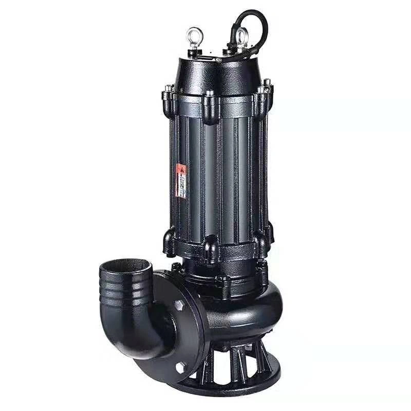
| Wastewater Treatment | Effluent, Greywater | Moving treated water through final filtration stages before ecological discharge (non-clogging variants are required for heavy sludge). |
Unmatched Advantages and Operational Benefits
Facility engineers and procurement teams consistently choose inline centrifugal systems over alternative positive displacement models for several compelling reasons.
- Seamless Pipeline Integration: The coaxial inlet and outlet design is arguably the greatest advantage. Installation is as simple as unbolting a section of pipe and bolting the unit in its place. There is no need to engineer complex ninety-degree pipe bends or pour massive concrete inertia bases.
- Compact Footprint: Particularly in the vertical configuration, these devices require a fraction of the floor space compared to traditional base-mounted end-suction models. This allows for the construction of smaller, more cost-effective mechanical rooms.
- Low Noise and Vibration: Modern units are precision-balanced. The direct-drive nature (lacking belts or external gearboxes) ensures that operation is whisper-quiet, a crucial factor when installed in residential towers, hospitals, or acoustic-sensitive environments.
- Cost-Effective Maintenance: The “back pull-out” design featured in many modern units allows technicians to remove the motor and impeller assembly for servicing without ever disconnecting the main casing from the pipeline. This drastically reduces system downtime and labor costs during routine maintenance.
How to Select the Right Equipment
Sourcing the correct machinery for a specific project requires careful calculation and consideration of the fluid dynamics at play. Selecting an underpowered or incompatible unit can lead to catastrophic system failure.
- Calculate the Required Flow Rate (Capacity): Measured in gallons per minute (GPM) or cubic meters per hour (m³/h), this defines the volume of liquid the system must move within a given timeframe.
- Determine the Total Dynamic Head (TDH): Head is the total resistance the fluid must overcome. This includes the vertical height the water must be lifted, plus the friction loss caused by the length of the pipes, elbows, and valves.
- Fluid Characteristics: Viscosity and temperature are vital. Pumping boiling water requires completely different mechanical seals than pumping ambient temperature groundwater. Furthermore, if the fluid is acidic, cast iron casings will corrode rapidly; 316L stainless steel or titanium must be specified.
- Motor Efficiency: Always look for high-efficiency motors (IE3 or IE4 classifications). Because these machines often run 24/7, a slight increase in motor efficiency translates to massive electrical cost savings over a decade of operation.
Best Practices for Installation and Maintenance
To ensure a lifespan that can easily exceed fifteen to twenty years, rigorous adherence to installation and maintenance protocols is required.
Pre-Installation and Alignment
Even though inline variants are easier to install, the pipes must be perfectly aligned before bolting. Forcing pipes to align by tightening the flange bolts places immense “pipe strain” on the casing. Over time, this stress will distort the casing, leading to severe vibration, shattered mechanical seals, and premature bearing failure. Always ensure the piping is independently supported by hangers so the machinery bears zero pipe weight.
Troubleshooting Common Anomalies
Table 3: Diagnostic and Troubleshooting Guide
| Symptom / Anomaly | Potential Root Cause | Recommended Corrective Action |
| Severe Vibration & Rattling | Cavitation (Fluid boiling due to low pressure) | Increase suction head pressure; check for blockages in the inlet pipe; lower fluid temperature. |
| Motor Overheating | Operating beyond design parameters (High flow) | Throttle the discharge valve to reduce flow rate and bring motor amperage back to normal limits. |
| Zero Fluid Discharge | System not properly primed; Air lock | Shut down immediately. Open the priming valve, bleed all air, and ensure the casing is 100% full of liquid. |
| Puddle Beneath the Shaft | Mechanical seal failure due to dry running | Replace the mechanical seal. Ensure dry-run protection sensors are installed in the control panel. |
Ongoing Preventative Maintenance
- Daily: Perform a visual and auditory inspection. Listen for grinding noises indicative of bearing wear. Check the floor for early signs of seal leakage.
- Monthly: Use a vibration analysis pen to record the vibration amplitude on the bearing housing. Log the motor’s operating amperage to ensure it is not slowly increasing over time.
- Annually: Schedule a brief shutdown to re-grease the motor bearings (if they are not sealed-for-life) and inspect the internal impeller for signs of pitting or erosion caused by suspended abrasives.
Smart Integration and IoT
The fluid transportation industry is undergoing a digital renaissance. The next generation of inline systems is being manufactured with built-in Internet of Things (IoT) sensors. These “smart pumps” continuously monitor their own vibration, temperature, and pressure differentials.
Instead of relying on a human technician to notice a problem, the equipment utilizes predictive maintenance algorithms. If the machinery detects the early onset of cavitation or a failing bearing, it can automatically throttle its own variable frequency drive (VFD) to protect itself and instantly send a diagnostic alert to a facility manager’s smartphone. This evolution transforms a simple mechanical device into an intelligent node within a modern smart building or automated factory.
Conclusion
Understanding the mechanics of fluid transportation is paramount for anyone involved in industrial engineering, municipal infrastructure, or commercial construction. By utilizing centrifugal force within a space-saving coaxial design, these devices have revolutionized how we design piping systems. They offer a masterclass in mechanical efficiency—delivering high volumes of fluid with minimal noise, a tiny spatial footprint, and exceptional long-term reliability. Whether sustaining the HVAC loop of a modern skyscraper or safely moving chemicals in a processing plant, their role as the quiet, beating heart of industrial infrastructure is absolutely undeniable.
FAQs
Why must the pump cavity be completely filled with liquid (primed) before starting the motor?
Centrifugal devices are designed to move heavy liquids, not air. Because air is significantly lighter and less dense than water, a rotating impeller cannot generate enough centrifugal force to create a vacuum if the casing is full of air. This condition, known as “air binding,” prevents the liquid from being drawn into the casing. Furthermore, the fluid itself acts as a vital coolant and lubricant for the mechanical seals; running the machine dry, even for a few seconds, can shatter the seals due to intense friction heat.
Can these specific inline devices handle highly viscous fluids or heavy sludge?
Generally, no. Standard inline centrifugal models are engineered specifically for low-viscosity, relatively clean liquids like water, light oils, or liquid chemicals. Highly viscous fluids (like heavy crude, molasses, or thick sludge) create immense internal friction that drastically reduces the impeller’s efficiency and overloads the motor. For thick sludges or fluids with heavy solid content, positive displacement mechanisms (like gear or diaphragm pumps) or specialized non-clogging centrifugal trash pumps are required.
How does a facility engineer decide between a vertical and a horizontal configuration?
The decision almost always comes down to spatial availability and maintenance resources. Vertical configurations are preferred in high-density urban developments (like commercial high-rises or underground municipal vaults) because they take up a fraction of the floor space. However, because the motor sits on top, removing it for maintenance requires vertical clearance and often a ceiling-mounted hoist. Horizontal configurations are chosen for industrial plants where floor space is abundant, as technicians can more easily slide the heavy motor backward for servicing without battling gravity or requiring overhead cranes.